
SMARTLOCKER
Keeping your things safe

THE DESIGN
SmartLocker has a functional and modular design that can be placed anywhere. The cabinets can be placed next to and on top of each other, creating fluidity in usage and with its orange facade it is easy to spot. The shape of the locker utilizes the space available for storing the users items. It is build to the maximum size defined by the design brief and consists of sheet metal and components made to fit industry standards.


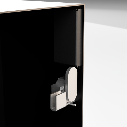
THE LOCKING MECHANISM
The locking mechanism is a simple bar turning 90 degrees up and down. The bar fits into a slot made from sheetmetal which is attached to the door of the locker (the door has been hidden to show the mechanism). On the lock is a small springloaded rod which opens the locker with a slight push. Above the locking mechanism is a compartment which can house the electronic components
THE HARDWARE
The locking mechanism is built around a Stepper Motor. The motor was chosen instead of a Servo Motor due to its durability and function. A 3d print of the design of the locking mechanism was made to fit the motor. The 3D print differs from the CAD model to make it suitable for tabletop testing. This setup is connected to a MCU-board which enables communication between the hardware and the app. Two LEDs in the colour red and green have been added to visualise if the locker is available or not (green for available and red for unavailable).
In the pictures below, the setup can be seen, and one might notice an arduino-board is connected to what could look like an I2C communication setup. This is not the case. The arduino board's only function is to be work as an electrical connection to ensure a correct voltage to the MCU board and the Stepper Motor.


THE SOFTWARE
To use Smartlocker, the user has to open the app and sign up using ones E-mail and choose a password for the locker. Simultaneously the user can choose which locker to use and reserve for which timeframe the use will occur. To avoid misuse it is only possible for the user to reserve a locker for a maximum of 24 hours.
After this step a confirmation E-mail is sent, with all of the information to the user, so the user will not need to worry about remembering the password and reservation. The user also has the possibility of checking if the locker is in use or not, and if it is open or closed.
If the user tries to open a locker using the wrong password a pop-up message "Access denied. Try again!" will be shown in the app. If the correct password is used the message "Your locker is open." is shown instead.
The setup was made using a combination of NodeRED, MQTT and Arduino. NodeRED was used for making the app, Arduino for the Hardware and locking-mechanism and MQTT was the link to connect the two.
A picture of the SmartLocker app can be seen below.


NodeRED
Sign-up and E-mail notification and Available/ Choose locker
The first step in developing the app was to set-up the Sign Up and E-mail notification flow. This meant that the app had to be able to save user information. This meant that the chosen password and E-mail had to be saved into two seperate variables called password and email.
After this information is saved an E-mail is sent to the user with the saved information.
The user can also choose which locker to use. This was done by setting up a menu and saving the chosen lockers name down as a variable called Lockername.
Show current date and time
The following step was to set up the reservation system. The system had to be able to reserve a specific locker for a specific timeframe. This means that the app needs to be able to register date and time. This was done by setting up a link to Worldtime API in a flow and making sure to update the information every minute.
Checking password
When the user tries to open a locker a password is required. This attempt is saved in a new variable called passwordcheck and compared to the initial password variable. If the two variables are the same the locker opens and a popup message is shown with the message "Your locker is open ". If they do not correlate the locker remains closed and the message shown in the app is "Access denied. Try again!".
Connection to MQTT
To set up the communication link between the app and the mechanism, MQTT was used. From NodeRED this connection was set up, by linking to the specific server and using output from the MCU which was sent as a msg.payload which can be used directly in NodeRED.
The setup of the code and its connections in NodeRED can be seen below.


Arduino
Establishing contact with the MQTT driver
The arduino code is programming the NodeMCU (ESP -12 modem) to establish contact to the given wifi by defining the ssid and the password. The WiFi loop only stops when contact is established. Afterwards it will read strings that is sent from a specific mqtt driver. The imported string will be saved in the global variable “Payload”, the imported topic will be saved in the variable “topic”.
If-statements
Afterwards some if-statements are made:
To check if the variable “Topic” is correct, an if-statement is made. If the value is “Test”, the next statements will be read. If not, nothing happens.
If the Topic is accepted, the next two if-statements are considered:
If the “payload” variable has the value “lock”, the steppermotor will turn clockwise 90°. The Stepper Motor has 2048 steps, and runs as a default counterclockwise. Therefore, the code tells the motor to turn -512 steps. Furthermore, the nodeMPU will send a digital HIGH output signal from pin D2 which is connected to a red LED. The output from D1 will be set to LOW.
If the “payload” variable has the value “unlock” the steppermotor will turn 90° counterclockwise and send a HIGH digital signal output from D1 which is connected to a green LED. The output from D2 will then be set to LOW.
If the Payload has any other value, these statements will not be executed.
Controlling the Steppermotor
The steppermotor is controlled by the digital pins D5, D6, D7 and D8. These pins are momentarily activated and deactivated to create electrical zones in the motor, and make it spin. To avoid to manually program each pin, we used the stepper.H library which automates this process.